 /
/  Add Reference Material / Profile Layout Command
- General Settings
-
Step-By-Step:
Reference Material -
Step-By-Step:
Reference Profile Layout - Tips and Tricks
- Related Tools
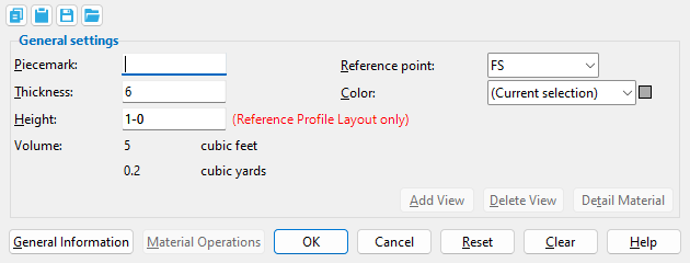
Piecemark: Blank or any character string (up to 61 characters). This is the submaterial piecemark .
If this field is left ' blank ', then when this material is generated (after you press " OK "), SDS2 piecemarking looks for materials in the current Job that are physically identical to this material and assigns to this material the same mark assigned to those materials. If no matching materials are found, SDS2 piecemarking assigns this material a piecemark using the appropriate piecemark prefix listed in Home > Project Settings > Fabricator > Member and Material Piecemarking .
Any ' character string ' that you enter must be unique -- the program does not let you enter a piecemark that has already been assigned to materials. If the material is exactly the same as previously added materials, the new material gets the piecemark of those previously added materials. On the other hand, if you are doing an Edit Material , all materials that are exactly like this material are re-assigned the unique mark you enter when this material is generated (after you press " OK "). The piecemark you enter remains a system piecemark , which means that it may be changed if you later edit a material just like this one and give that material a different piecemark.
Note: A submaterial mark is not yet assigned when this window opens for an add operation. A piecemark is shown here if you open this window using Edit Material . For the current quantity of materials assigned this piecemark, see the " Current quantity " listed on this material's General Information window.
Report Writer:MemberMaterial.Material.MinorMark
Advanced Selection:MinorMark
Parametric model module:MinorMark
Thickness: The thickness (in the primary dimension " Units " or other units ) of this Reference Profile Layout or Reference Material. Changing the " Thickness " will update that Reference Material in the 3D model when you press " OK ."
|
t = thickness. For a Reference Profile Layout in a plan view, the thickness is the edge of the Reference Material that you can see in that view. This thickness is centered around the work points of the layout. |
|
t = thickness. For a Reference Material laid out in a plan view, the thickness dimension is vertical and therefore cannot be seen in the plan view. This thickness is oriented with respect to the " Reference point ." |
Report Writer:XXXXX . Thickness
Advanced Selection:Thickness
Parametric model module:ThicknessAlso see: The " Reference point " sets how a Reference Material 's " Thickness " is oriented with respect the work points that were located to add the Reference Material .
Height: The distance (in the primary dimension " Units " or other units ) from the near side edge of the Reference Profile Layout to its far side edge. This does not apply to Reference Materials.
|
h = height of a Reference Profile Layout . |
Report Writer:XXXXX . Width
Advanced Selection:Width
Parametric model module:WidthAlso see: The " Reference point " sets how the Reference Profile Layout 's " Height " is oriented with respect to the work points that were located to add the layout.
Volume: read-only . The calculated volume of the reference material. The volume is expressed in both cubic feet and cubic yards if you are using ' Imperial ' units. For ' Metric ' units, volume is expressed in cubic meters.
A Reference Material 's " Thickness " is used to calculate the volume.
A Reference Profile Layout's " Height " and " Thickness " is used to calculate the volume.
Reference point: FS or Center or NS . This affects how a Reference Material 's " Thickness " or a Reference Profile Layout 's " Height " is oriented with respect to the plane in which its work points were located. Editing reference material to change its " Thickness reference point " updates that material in the 3D model when you press " OK ." Work points for the following three examples are all laid out at an elevation of 100 feet.
Reference point = FS |
Reference point = Center |
Reference point = NS |
If the work points of the Reference Material were located at a particular plan view elevation, ' FS ' places the bottom of the Reference Profile Layout or Reference Material at that elevation.
If the work points of the Reference Material were located at a particular plan view elevation, ' Center ' places the middle of the Reference Profile Layout or Reference Material at that elevation.
If the work points of the Reference Material were located at a particular plan view elevation, ' NS ' places the top of the Reference Profile Layout or Reference Material at that elevation.
Color: A predefined color or a Custom Color . This is the approximate color of the Reference Profile Layout or Reference Material when it is displayed in a solid form . The material is transparent no matter what solid form it is displayed in.
![]() Copy, Paste, Save, Load buttons:
Copy, Paste, Save, Load buttons:
- The position of these "form" buttons on the window tells you what settings they apply to. Click here for more information.
- You can
 Copy the settings on this window, then
  Paste those settings to a different edit window of the same type.
- You can
 Save the settings on this window to a file stored in a global folder that is used by your current version of SDS2. Give the file a name that will help other users identify its purpose. You can
  Load a saved file to replace the settings on this window (except Piecemark) with the settings that are stored in the file you select.
- When editing multiple windows at the same time, Paste and Load replace mixed entries to a single field with a single entry. Copy and Save ignore fields with mixed entries, treating them as if they have no entry or do not exist.
| Special Buttons for Detailing this Material (these do not appear for Add operations) |
||
|
|
|
|
| This button opens a window with a list of preset views . Each preset view that you select on this list is drawn on the submaterial detail when you Detail Submaterial . | This button opens a list of views you can delete. If the material has only one view, you get a warning instead of a list of views since you cannot delete the current view. | This button does a Detail Submaterial on this material. Newly added views are drawn on the detail. Deleted views are not drawn. |
" General Information " opens the General Information window, which provides additional information and settings that pertain to this Reference Profile Layout or Reference Material .
Tip: You can use the General Information window to change the material's " X ," " Y ," or " Z " global coordinates (and thus reposition the material within the 3D model).
Also: A " Properties " button at the bottom of the General Information window lets you set Custom Properties for this material.
Material Operations opens the Material Operations window.
Tip: You can use the Material Operations window to delete or edit a stored material operation.
Note: Not all material operations are stored in the Material Operations window. Material Fit Exact, Material Fit Cope, Material Fit Notch, and Cut Layout are the only material operations that are stored here.
OK (or the Enter key) closes this window and applies the settings on it to the material(s).
Defaults: Even if you did not make any changes on this window, pressing OK causes many of the General settings on this window to be applied as the defaults for the next material of the same type that is added in your current session of Modeling.
If you opened this window to edit a single material (single-edit), the Change All Options & Warning List opens after you press the OK button. You can use that window to cancel your changes or, if other materials with the same submaterial piecemark exist, apply your changes to those other materials. Also, if a Cut On Plane or related cutting/bending/fit operation (that does not get stored in the Material Operations window) was previously done on this material, you are given the option to undo that operation.
If you opened this window to edit multiple materials (multi-edit), the Change All Options & Warning List does not open after you press the OK button. Also, if a Cut On Plane or related cutting/bending/fit operation (that does not get stored in the Material Operations window) was previously done on this material, you are not given the option to undo that operation.
Cancel (or the Esc key) closes this window without saving any changes.
Possibilities: If you are adding a new material, Cancel brings you back to the work point location step (step 2) in the add operation. For an edit material operation, Cancel ends the operation.
Tip: When you open this window to review information only -- and you do not want to set the defaults for the next-added rectangular plate -- the best way to close this window is to press Cancel.
Reset undoes all changes made to this window since you first opened it. The window remains open.
Note: The settings shown on this window when it first opens for the adding of a material are the settings of the last-added or last-edited material of the same type (unless you exit Modeling in the meantime).
Clear fills out this window with default settings when adding material. It is disabled during an Edit Material operation. These are the same defaults that are applied when the first new material is added during a session of Modeling in which no other material of the same type has been edited. For example, Clear automatically selects the default Steel grade and zeros out the all Left/Right End Settings.
To Add Reference Material to a member
1 . Click the Reference Material icon, which is pictured above. The icon can be found on the Material page > Add section. Select a member you want to add the material to.
▸ Preselect a member to enable the Members contextual page and click the Reference Material icon found in the Mateials/Components section.
Alternative: Invoke Reference Material using the Find Tool by searching the command name and clicking the icon, which is pictured above.
Learn more about alternative methods for launching commands.
2. Skip this step if you already selected a member in step 1.
2a: The status line prompts you to " Select member ." Select One Item mouse bindings are activated so that you can left-click ( Select ) the member you want. This prompting also occurs when more than one member is selected or if, for example, a material or bolt is selected.
3.Locate- Pan -Return mouse bindings become active along with various Locate options.
3a: Define the layout with 3 or more sides, this will be the exterior of the reference material layout.
Note : You can middle-click ( Complete ) after having located at least three points to have the program automatically locate the last point as the location of the first point or you can draw a closed shape.
Note : If you accidentally left-click ( Locate ) at a point you do not want, hold down Shift and middle-click ( Remove ) to remove that point. You can remove as many points as you like, then continue locating points.
4. The status line prompts, " Locate material dimension reference point. " Left-click ( Locate ) a reference point that you want auto detailing to dimension to when you Detail this member. Right-click ( Return ) cancels the material add.
5. The Reference Material window opens, press " OK ." When given the option to rotate the material, press " OK ."
|
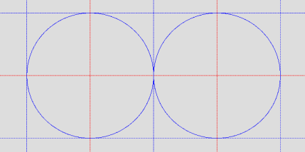
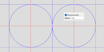
1 . Lay out construction lines and circles so that there are vertexes. |
|
2 . Invoke Add Legacy Miscellaneous Member and select " Reference Material ." Check the box for " Round corners " and enter a " Radius " equal to that of the construction circles. |
|
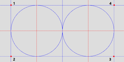
3 . With corner rounding on, locate points until you have a closed shape. Then locate the dimensioning reference point. The points located in this example are marked 1 through 4. |
|
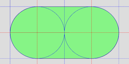
4 . Enter the " Thickness ," etc., then press " OK ." When given the option to rotate the material, press " OK ." |
|
5 . A solid transparent representation of the Reference Material you specified is now a part of the 3D model. You are looking at the near side of the Reference Material . |
To Add Reference Profile Layout to a member
1 . Click the Reference Profile Layout icon, which is pictured above. The icon can be found on the Material page > Add section.
▸ Preselect a member to enable the Members contextual page and click the Reference Profile Layout icon found in the Mateials/Components section.
Alternative: Invoke Reference Profile Layout using the Find Tool by searching the command name and clicking the icon, which is pictured above.
2. Skip this step if you already selected a member in step 1a.
2a: The status line prompts you to " Select member ." Select One Item mouse bindings are activated so that you can left-click ( Select ) the member you want. This prompting also occurs when more than one member is selected or if, for example, a material or bolt is selected.
3. Locate- Pan -Return mouse bindings become active along with various Locate options.
3a:Select two or more points, this will be at the center of the reference material's thickness.
4. Middle-click ( Complete ) to tell the program that you are done with the Reference Profile Layout .
5. The status line prompts, " Locate material dimension reference point. " Left-click ( Locate ) a reference point that you want auto detailing to dimension to when you Detail this member. Right-click ( Return ) cancels the material add.
6. The Reference Material window opens, press " OK ." When given the option to rotate the material, press " OK ."
To get a curved layout, first lay out a construction circle where you want the Reference Profile Layout to be curved. Then draw construction lines that are tangent to that circle. When locating points at intersections that are tangent to the construction circle, turn on corner rounding and set the " Radius " equal to the radius of the construction circle.
|
1 . Invoke Add Legacy Miscellaneous Member and select " Reference Profile Layout ." Left-click ( Locate ) a point on the circle tangent to a line that forms the vertex located in step 2. Also see to add . |
|
2 . Check the box for " Round corners " and enter a " Radius " equal to the radius of the circle. Left-click ( Locate ) a point at the vertex of construction lines that are tangent to the circle. |
|
3 . With corner rounding still on, left-click ( Locate ) a point at the vertex of construction lines that are tangent to the construction circle. |
|
4 . With corner rounding still on, left-click ( Locate ) the last point. Note that this point is tangent to a line that forms the vertex located step 3. |
|
5 . Middle-click ( Complete ) to tell the program that you are done with the Reference Profile Layout . |
|
6 . Left-click ( Locate ) a reference point that you want auto detailing to dimension to when you Detail this member. |
|
7 . Enter the " Thickness " and " Height " of the Reference Material ., press " OK ." When given the option to rotate the material, press " OK ." |
|
8 . The Reference Profile Layout you specified is now a part of the 3D model. You can see through its Reference Material regardless of the solid form in which the member is displayed. You are looking at the thickness of that Reference Profile Layout . |
- Existing member (automatic for Reference Material )
- Use this point as new base position (useful DXDY option)
- General Information window (may be opened from this window)
- Submaterial piecemark (each unique material identified by)
- Submaterial detail (2D drawing of a material)
- Miscellaneous Member Edit
- Miscellaneous Member Types
- Legacy Miscellaneous Member Edit
- Legacy Miscellaneous Member Types

